Transmission range

Established Texecom Ricochet
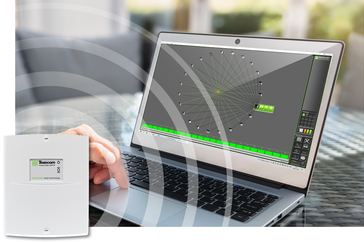
Our Ricochet mesh networking wireless technology delivers more performance than any other wireless security system. Ricochet enabled wireless devices receive and repeat wireless transmissions from other devices. The size, scalability and range of the entire system are extended as wireless signalling is no longer limited by point-to-point communications. The range of a Ricochet enabled wireless system is greater than conventional point to point systems, with multiple devices capable of relaying messages to and from even the most remote locations in a building.
Maximum wireless range
Wireless data transmission occurs through radio waves. In optimal scenarios, with no obstructions or interference along their path, these waves travel the shortest route from the transmitter to the receiver. The maximum communication range is achieved in such unobstructed open spaces. This range serves as a widely accepted standard for evaluating radio technologies and equipment employing radio communication.
Factors affecting the radio communication range
Despite the maximum wireless range being the accepted benchmark, in day-to-day scenarios not all applications have a fully clear path with obstacles or third-party interference needing to be considered in these situations.
Obstacles
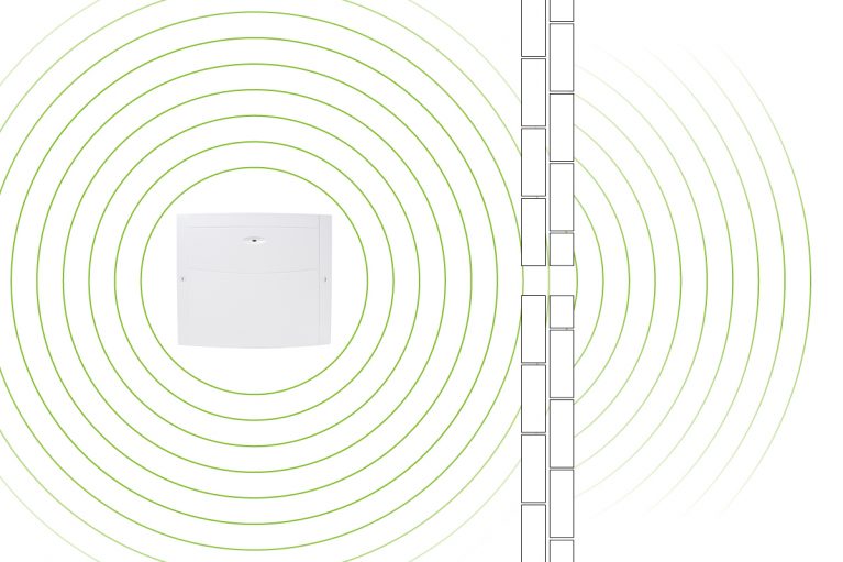
In every day conditions, radio waves collide with obstacles. These obstacles vary in their interaction with waves, with some allowing passage, others reflecting, and some absorbing the radio waves. The nature of these obstacles depends on their material, shape, and thickness. Factors like rain, snow, dust, and even high humidity can serve as obstacles, similar to physical objects like people. Generally, when a radio signal encounters an obstacle, it weakens, losing some of its power.
Inteference
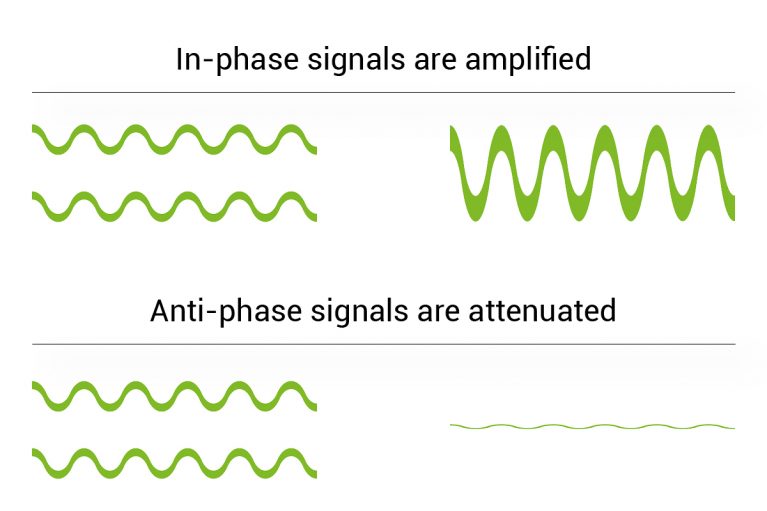
Radio waves on the same frequency can cause interference. Further interference can also be caused by reflected signals from the same transmitter caused by obstacles. These may not cause signal attenuation (signal loss) but can impact the range of the device.
Note: Moving a wireless device slightly can eliminate potential dead spots.
Diffraction
Diffraction is when radio waves meet an obstacle which contains small holes but is able to pass through without signal atteunation (signal loss).
Note: Moving a wireless device slightly can eliminate potential dead spots.
Can different obstacle materials affect radio signals?
Different materials between the wireless receiver and the devices have varying effects on the systems wireless signal strength.
Some materials can reflect or absorb radio waves, whilst others may have minimal impact. The higher the signal absorption coefficient and the thicker the obstacle, the stronger the impact on radio transmissions.
Below we have listed some examples of these materials and the effect they may have on wireless performance.
Less than average
Low signal absorption coefficient – up to 3 dB (50% power loss, transmission range 30% shorter)
Dry red brick
90mm thickDry wood
80mm thickGypsum board
100mm thickGlass
15mm thickAverage
Average signal absorption coefficient – 5-20 dB (Power reduces 10 times; transmission range reduces by 60%)
Brick
250mm thickConcrete
100mm thickBreeze block
200mm thickMasonry
200mm thickHigher than average
More than 20 dB. Signal absorption coefficient (Power reduces more than 100 times; transmission range reduces by 70%)
Concrete
300mm thickMetal beams
Aluminum and steelReinforced concrete
200mm thickCorrugated metal
Sheet metalCan obstacles reflect signals?
At our frequencies, an object with a straight surface and a size of at least 30 × 30 cm will reflect the signal reducing signal strength up to 10%.
Note: All surfaces reflect radio signals to some extent. However, metals and mirrors do so to a greater extent.
How wireless device positioning affects signal range
Different environments can provide challenges when installing a wireless security system. Click on the numbers below to see how device positioning affects signal range.
Good practice – Detector mounted at a the correct height and away from radio obstacles. The radio signals are strong and reach the control panel.
Good practice – control panel location is key for improving a wireless system. A central location away from radio obstacles will improve radio range and help create a network with all the other wireless devices.
Good practice – Mounting a Micro Shock-W on a metal window frame will require the deep base to allow transmission of the radio signal.
Good practice – A central location away from radio obstacles will improve radio range and help create a good signal connection with the control panel.
Bad practice – Mounting a Micro wireless device on a metal window frame with the shallow base will cause the radio waves to be absorbed resulting in poor signal strength.
Bad practice – Mounting the control panel too low can cause the signal to propagate into the floor. It’s also surrounded by other electrical devices and obstacles which affect the radio transmission. In this case the radio signal is poor.
Bad practice – Mounting the Capture detector close to obstacles such as a metal vent will absorb the radio signals resulting in poor transmission.
Bad practice – Mounting the Odyssey X-W adjacent to a metal vent will cause the radio signals to the control panel to be blocked.
Good practice – Odyssey X-W mounted away from metal obstructions such as fork lift trucks. Within good range of the wireless expander.
Good practice – Impaq SC-W is the ideal product to use for a roller shutter door. The terminal inputs allow for external roller shutter contacts to be connected. This allows these devices to be added to the wireless network.
Good practice – 2 Premier Elite 32XP-W’s provide full coverage of the system. They are mounted at least 2m high and free from obstructions.
Good practice – Positioned away from radio obstacles and in close range of the wireless expander.
Bad practice – Mounting a detector next to a junction box and near metal shelving are major radio obstacles.
Bad practice – Impaq SC-W mounted near to where fork lift trucks are parked (or other large metal objects).
Bad practice – Not to be used on metal shutters/doors.
Bad practice – Hiding a wirelss panel or wireless expander in ceiling voids, risers, cupboards etc, in the corner of a system will result in signal loss and therefore poor network performance.
Battery life performance
Ricochet enabled devices are meticulously crafted to elevate battery performance, setting a new standard for longevity and reliability. Our designs are tailored to maximise the potential of each battery, ensuring optimal functionality and extended product life.
Maximising Battery Performance
This shows how activations on detection devices have an effect on battery life:
In most scenarios, the default mode is the best choice, but the option of changing the mode can allow installers to balance performance with battery life for devices in different situations.
For example, for a Micro Contact or Impaq SC-W fitted to a door that is frequently opened and closed during the day, the battery life could be extended by setting the mode to Auto or Hybrid.
| Device | Approx Battery Life (activated every 2 min) | Approx Battery life (activated hourly) | Default Mode |
| Micro Contact | 1 year | 3 years | Always Awake |
| Micro Shock | 1 year | 3 years | Always Awake |
| Impaq SC-W | 1.25 years | 3.5 years | Always Awake |
| Capture P15-W/Q20-W/CQ-W | 2 years | 4 years | Auto |
| Capture D20-W/CD-W | 1.5 years | 4 years | Hybrid |
| External TD-W | 2 years | 4 years | Auto |
Battery Modes
| Mode | Description | Pros | Cons | Restrictions |
| Always Awake | Devices report every activation | Maximum system performance. Best used on entry/exit zones | Frequent activations will affect battery life so not suitable for high traffic areas | Not suitable for Dual Tech PIRs |
| Auto | Devices only report activation after a period of inactivity | Good balance of performance especially for PIRs | Not always suitable for entry/exit zones or exit terminators | Not suitable for Dual Tech PIRs |
| Hybrid | Devices only report activations when the system is armed | Maximises battery performance | Devices must be woken up when arming the system (preparing to arm process) | Must be used for Dual Tech PIRs |
Recommended Battery Brands
There are many cheaper brands that state the same capacity, but due to differences in measurement techniques and differenced in performance under pulse loads, lifespan can be dramatically different.
| Device | Battery Type | Recommended Brands |
| Micro Contact/Micro Shock | CR2450 | Varta CR2450 Procell CR2450 |
| Impaq SC-W/SmartKey | CR2 | Varta Industrial Pro CR2 Duracell Lithium CR2 Procell CR2 |
| Capture | CR123A | Varta Industrial Pro CR123A Duracell Lithium CR123A Procell CR123A |
| External TD-W/LDCP-W/Odyssey-W | AA Lithium | Energiser AA Ultimate Lithium |
| Premier Elite OH-W | AAA | Duracell AAA Procell AAA |
Why Ricochet technology?
Ricochet enabled wireless devices receive and repeat wireless transmissions from other devices. The size, scalability and range of the entire system are extended as wireless signalling is no longer limited by point-to-point communications. The range of a Ricochet enabled wireless system is greater than previous systems, with multiple devices capable of relaying messages to and from even the most remote locations in a building.